FAQs
Dangers of Motor Controllers Without Current Limitation
Many DC motor controllers on the market are designed with significant functional limitations to reduce costs. One critical shortcoming is the lack of active current measurement and regulation.
Why Current Limitation is Crucial
- DC motors can draw 3 to 10 times their rated load current during startup or sudden acceleration.
- These short but intense overload conditions are especially dangerous for the internal power electronics stage.
Without active current limitation, the power stage can immediately burn out, resulting in irreversible damage to the controller.
The Solution: Ultra-Fast Current Limitation
The only effective solution is selecting a motor controller equipped with proper and ultra-fast current limitation.
Our motor controllers are supervised by a highly efficient ARM Cortex microprocessor, which performs more than 100,000 measurements per second. If overload conditions occur, the processor instantly intervenes to keep the output within the safe operating range.
Advantages of Current Limitation
This current limitation function not only serves as a protective feature but also enables the motor to deliver precise and controllable output torque across the entire range of operation.
By choosing a motor controller with advanced current regulation capabilities, you can ensure both the safety of your system and optimal motor performance.
Essential Design Criterials for DC Motor Controllers
When designing motor controllers, there are several important criteria to ensure durability and reliable operation. Below, we highlight some critical design aspects.
Adequate Buffer Capacitance
A key element in motor controller design is integrating sufficient buffer capacitance.
PWM motor controllers (Pulse Width Modulation) achieve near-lossless regulation by rapidly switching the output between 0 and the supply voltage.
DC motors, due to their mechanical inertia, respond very slowly to these rapid fluctuations, making the switching imperceptible in terms of output speed variation.
However, the sudden pulse-like load demands cannot always be served by the power source (e.g., a battery located several meters away) large onboard capacitors act as a temporary buffer, supplying the necessary energy during these high-current pulses.
Importance of Sufficient Capacitance for High Performance
- The power transistors can only efficiently handle rapid switching if the buffer capacitors provide the required current surge without significant voltage drop.
- For this reason, the onboard capacitors must:
- Be capable of sustaining high current flow.
- Operate without excessive heating, which could lead to component failure.
Risks of Insufficient Capacitance
Many motor controllers on the market, to reduce board size and costs, include either too few capacitors or capacitors with low current ratings. Insufficient capacitance can result dangerous overvoltage spikes within the circuit. Long-term issues like overheating, which accelerates capacitor drying and reduces their lifespan.
Optimal Solution: High-Quality Capacitors with Low ESR
- The best way to mitigate these issues is by designing motor controllers with:
- Sufficient capacitors for energy storage.
- Low ESR (Equivalent Series Resistance) capacitors to handle high currents efficiently.
- Proper electrical and thermal design ensures optimal performance and durability under continuous operation.
- The best way to mitigate these issues is by designing motor controllers with:
For more details on capacitor selection and design principles, see our article on Buck Converter Design
How to reverse DC motor Direction Reversal with Relays
In many applications, it’s necessary not only to control the speed of a motor but also to reverse its direction. Below, we describe traditional and modern approaches to achieving motor direction reversal.
Reversing Motor Polarity with Relays
A traditional yet reliable method for reversing the direction of a DC motor involves using a double-circuit relay or contactor.
This setup allows for a straightforward change in the polarity of the voltage applied to the motor.
Drawbacks of Mechanical Switches
While this method is simple and widely used, it comes with some challenges:
- Contact reliability issues can arise over time.The copper and bronze contacts of relays may carbonize due to arcing, leading to poor conductivity.
Over time, the switching reliability may degrade, resulting in inconsistent operation.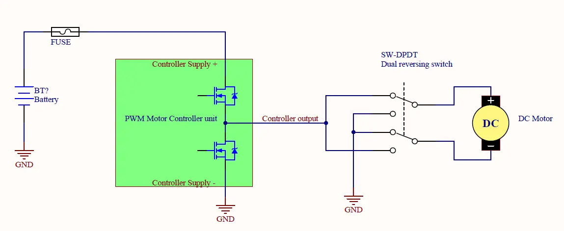
Reversing switch
Modern Solution: H-Bridge Controllers
A more effective and reliable alternative is using a motor controller with an H-bridge configuration for the output power stage.
Benefits of H-bridge-based controllers include:
- No mechanical wear, ensuring long-term reliability.
- Fast and efficient switching using semiconductor components.
- Less wiring and less additional component in the system
- The ability to handle high-speed direction changes without introducing significant delays.
By transitioning to H-bridge motor controllers, you can achieve precise, efficient, and durable direction control, avoiding the common problems associated with mechanical relays.
Advantages of the H-Bridge Motor Controllers
4Q (Four-Quadrant) or Full H-Bridge motor controllers are advanced systems designed for complete electronic control of the motor’s output polarity. This eliminates the need for mechanical relays. These controllers support both dive and regeneration operational modes:
Advantages of this approach compared to relay-based direction control:
No Relays Required
- Simpler Design: There’s no need for relays, complex wiring, or additional relay control circuits.
- Integrated Functionality: The motor controller itself electronically handles the polarity reversal to control motor direction.
Increased Reliability
- Relay-based systems are prone to contact wear and issues such as carbonization of contacts, leading to degraded performance over time.
- Electronic switching in H-bridge controllers eliminates these mechanical failure points, providing longer-lasting and more reliable operation.
Regenerative Braking
A significant advantage of 4Q controllers is their ability to support regenerative braking.
This feature allows the motor to act as a generator during braking, converting mechanical energy into electrical energy and feeding it back to the battery.
Regenerative braking is useful when actively slowing down a spinning motor, improving energy efficiency and reducing wear on mechanical braking systems.
Smooth and Precise Control
The fully electronic design enables seamless switching between directions and braking modes, resulting in smoother operation.
The controller can handle high-speed transitions without the delays or wear associated with mechanical relays.
By choosing a 4Q full-bridge motor controller, you gain a compact, reliable, and energy-efficient solution for controlling motor direction and braking, far superior to traditional relay-based methods.
Difference Between One-Way and reversible controllers?
Both unidirectional and variable H-bridge controllers are available in our webshop.
It is worth choosing according to your needs.
for example, you do not need a variable output to control fans, pumps, heating elements or LEDs.
Operating Motor Controllers with Various Power Supplies
DC motor controllers can be used from any battery power supply without special settings.
In the case of a DC power supply, a small note is that in some cases, depending on the application the drive is used for, it may be necessary for the regenerative feedback to be disabled or set to a low value. This is necessary because DC power supplies cannot or only have a limited ability to absorb the restored current. This is possible if the motor is used in a place where active braking and recuperation takes place.
In such cases, the feedback can be switched off or downregulated in our DC motor controllers.
Another simple option is to protect the motor controller against high voltage tripping.
Each of our controllers has a basic programmed maximum value, but this can be changed at any time if necessary, or we can even set the desired value on request.
What kind of protection might be necessary for battery operation?
In order to protect the batteries, it is important to ensure that the voltage of the battery cells is never lowered below a minimum value. Although there are separate circuits that can be installed for this, a simple solution is provided by the low voltage switch-off protection that can be set in the DC motor controller
All our controllers have a basic programmed minimum value, but if necessary, this can be changed at any time or we can even set the desired value on request.
Can I Connect the Motor Controller to an AC Power Supply?
Not! AC power supply cannot be connected!
In such cases, a rectifier diode bridge is required, but it should be expected that the rectified DC voltage will be 1.42x higher when connected to the DC motor controller.
Inductive current of DC motors and the role of a freewheeling diodes.
A recurring question is whether the controller can handle the motor’s inductive “spikes” and whether there is a suitable freewheeling diode. Our controllers are designed in such a way that the inductive current of the motor is led by a more efficient solution, the active half-bridge or H-bridge configuration.
Simple controllers only use an undersized diode is used for this task. Such controllers usually fail immediately at low speeds and high load currents.
Our electronics have an active half-bridge or H-bridge solution, which can conduct the inductive load currents symmetrically in the entire speed and load range.
What kind of cooling is required for the motor controller?
Our HLXH and FRXH and DXH series controllers do not require extra cooling or heatsinks due to ultra-low losses. Of course, in a warm environment, it is never disadvantageous to use a ventilator.
With our regular HL and FR models additional heatsink is needed if you buy the PCB board version of controller.
How can I measure motor current or battery or power supply voltage?
The current, temperature and voltage of the motor are continuously measured and monitored by all our DC motor controllers. If these data are needed, these data can be read continuously on the TX RX connections via serial communication.
A detailed description of this can be found in the data sheets of the motor controllers.
Another possibility is the ULCD v1.0 DC motor display, with which all internal parameters can be easily set and saved and continuously monitored.
How can I change the direction of a series-excited DC motor?
Reversing the of rotation of DC motors with series-excited coils requires different kind of solutions. In order to be able to change the direction, it is only possible if only the poles of the excitation coil (S1-S2) are changed. There are several solutions for this task.
Solution 1: Using a High-Current Contactor
A high-current contactor with a dual switching circuit can reverse the field winding polarity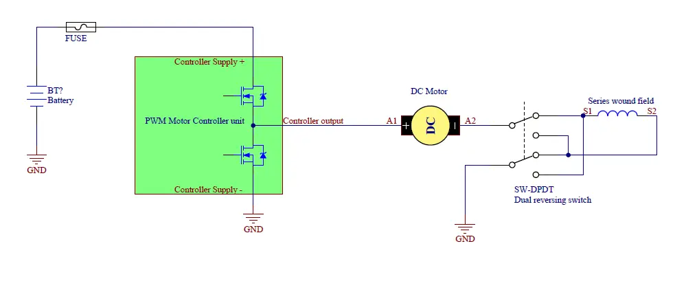
The field winding is connected in series with the motor armature. The contactor switches the polarity of the S1-S2 terminals.
The entire motor load current flows through the field winding. Reversing the field polarity reverses the magnetic field, which changes the motor’s rotation direction.
Solution 2: Using a Separate Controller for the Field Winding
This solution uses a controller to manage the field winding’s polarity and current independently.
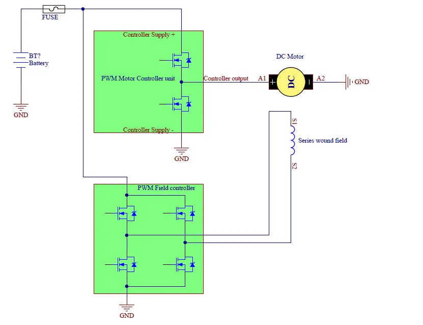
The armature (A1-A2) is connected to one controller for speed regulation.
The field winding (S1-S2) is connected to a separate H-bridge controller that:
- Supplies constant current.
- Allows polarity reversal for directional control.
Solution 3: Using an Integrated Controller
An integrated motor controller can simultaneously manage both the armature and field winding.
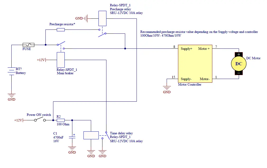
Is a precharge resistor necessary when connecting the motor controller connections?
A precharge resistor is a simple but necessary addition at the supply point of electronic controllers, whose task is to reduce the peak value of the switching transient current and thereby prevent an impulse above the supply voltage from forming at the input of the controller.
This phenomenon arises from the fact that the large amount of capacitors placed on the DC motor controllers receive the full supply voltage in an uncharged state at the moment of switching on. Due to the low resistance of the thick power supply wires, the internal resistance of the accumulators is typically low.
It is worth paying more attention to this phenomenon in the following cases:
- If the maximum voltage of the motor controller is close to the supply voltage.
- If the supply lines are long and their inductance is not minimized
- Batteries with very low internal resistance
The voltage spike can be reduced by minimizing the length of the supply wires and reducing their self-inductance by wrapping them tightly around each other.
For typically higher supply voltages where there are high-capacity accumulators, such as electric vehicle drives, it is worth placing a precharge resistor in parallel with the input main switch. The purpose of this is to charge the control capacitors before the delayed switching on of the main switch. An example of this connection is shown below:
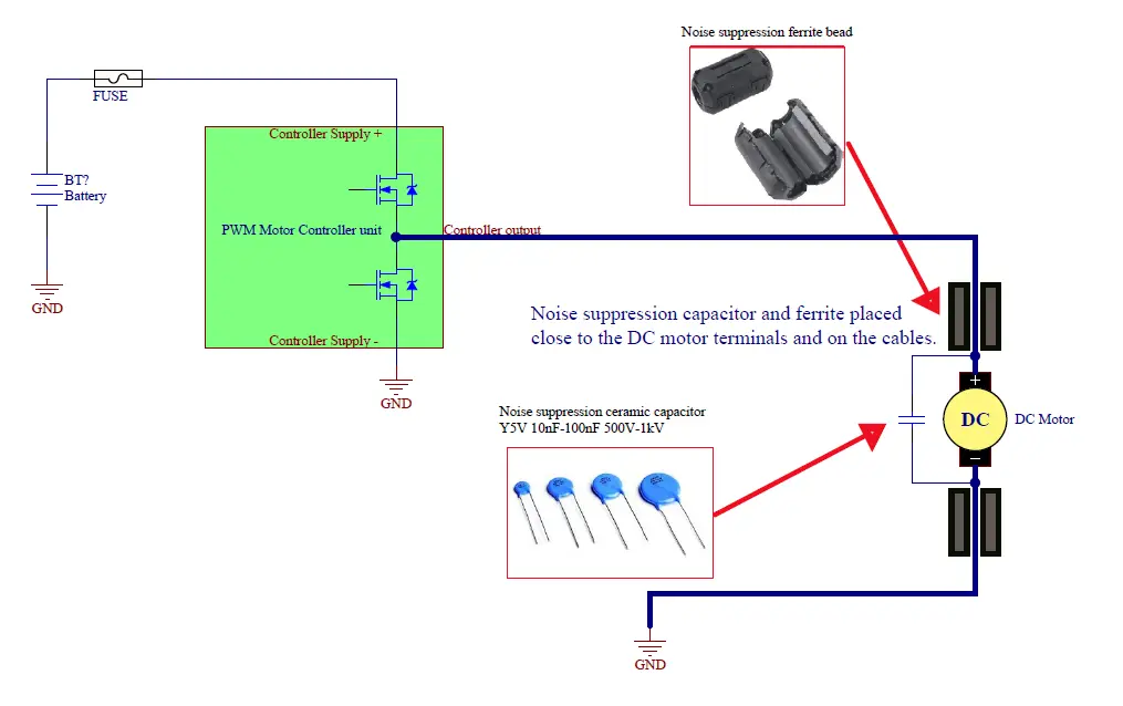
Noise generation of DC motors, how to protect against it?
All DC motors emitted high frequency noise. This noise is generated by tiny sparks between the carbon and bronze brushes and the commutator plates. These high-frequency noises and disturbances can not only disturb the surrounding electronic circuits, but in rare cases they can also cause abnormalities by returning to the motor control electronics.
The only way to protect against radiated electromagnetic noise is by shielding the motor, which in many cases is unsolvable and rather neglected due to its complexity. What we can do, however, is to minimize the disturbance returning to the wires.
This can be achieved by placing ceramic capacitors on the motor terminals. These ceramic capacitors, designed for interference filtering, with their almost zero impedance at high frequency, almost completely absorb the spikes produced by the brushes.
In addition to using a capacitor, an even better result can be achieved if ferrite boud rings are applied to the wires of the motor cables. These small cores do not block the current flowing through the motor, but with their high impedance at high frequencies, they block disturbances from the motor.
What is needed for this may be a 10-100nF 1kV for the middle and a 1nF/1kV Y5V type capacitor, which will be effective in the high frequency range.
The connection of the capacitor and ferrite is shown in the circuit below:
Can the DC motor controller be used for BLDC motor controllers?
Not. BLDC motors are made with a three-phase winding, which can only be operated with an AC drive.
Controller electronics are currently under developments.
Can I connect an Arduino, Raspberry Pi, PLC, or other digital devices to the motor controller?
Yes. PWM modulating signals can be used from any development panel or all functions can be controled with direct serial communication commands. Detailed information on serial communication can be found in the data sheets.
You can also find detailed instructions how to implement the serial communications in your embedded uPC system.
What speed sources can I use for the motor controllers?
For the DC motor controllers we have, you can use the following options:
- 1-10 kΩ potentiometer for speed control.
- Standard 5V Hall effect pedals and levers can also be used, which provide an output voltage ranging from 0.8V to 4.2V.
- 0-5V analog signal from another source for speed regulation.
- PWM signal form other uPC or wirelles receiver
- Serial communication form other device
With a few exceptions, all options are available in all of our controllers. For the available options please check on our specific motor controllers datasheets.
Can I use a limit switch with the motor controller?
Yes. Limit switches can be connected in various configurations. Most DC motor controllers have an Enable (EN) pin, which can be used to easily disable the output power stage. If necessary, we can program the electronics to automatically detect the limit switches and respond accordingly.
How can I communicate with the motor controllers?
Our DC motor controllers can be controlled with direct serial communication commands for all functions. Detailed information about serial communication is available in the datasheets.
Additionally, Arduino libraries and C example functions are available for easy integration.
Can the controllers be controlled via Modbus protocol?
If needed, we can program the controllers to use the Modbus RTU protocol.
Can I control the motor controllers wirelessly?
Yes currently, two types of remote control modules are available to adjust motor speed and direction.
We have available wirelles controll keys and wirelles stomp switches available.
These modules can be found here:
Can I use an RC remote control with the motor controller input?
Yes. Each motor controller can receive PWM signals from an RC receiver.
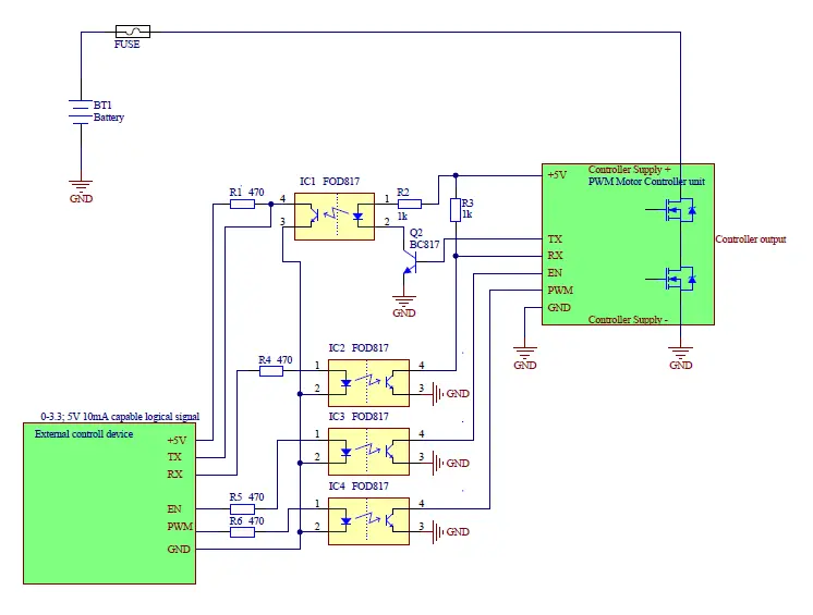
Is the motor controller input electrically isolated? Why is this important?
No, the motor controller inputs are not electrically isolated. In certain applications, where the controller signal source operates at different potentials, an optical isolator may be necessary. This can be easily implemented using optocouplers, as detailed in the diagram below, or by using an available optical isolation circuit, which can be used for isolating serial communication or logic and PWM inputs.